
Ratte Control Switch
It is over 6 months since I installed my Ratte Auto Monitor Switch (Ratte AMS from now) and I’m still as thrilled over the functionality as I was when I installed it. As I have said before, if you have more than one display port in your Amiga I really do recommend you to check if you can use Ratte AMS in your system.
As standard the Ratte AMS is set to automatically switch between RTG and Native via software that is installed on your Amiga.This can easily be change by changing position on a jumper. By doing this you can manually choose between.
- Automatic mode
- RTG Only mode
- Native mode
The problem here is that Ratte AMS usually is installed inside your computer and it will be some job to change the needed jumper. What you can do is to add a 3-way switch that has on-off-on to control it from the outside, but the switches I found was not as nice to look at and I would rather only use Auto-mode instead of adding such switch.
I took some time to Google the internet for ideas and suddenly I found a person called mfilos that had made a pretty neat solution. He had taken the idea to a whole other level but adding a 12mm momentary switch, two relays and an IC to control it. The switch fitted like a glove in the front of Amiga 4000 and it replaced the standard lock-mechanism. Did I mention that the switch also had a nice built-in blue LED?
His solution was to have the LED on while Ratte AMS was either in Auto or RTG mode to indicate status.
My first thought was to follow mfilos solution by the book but then it would not be a challenge. I then decided to build a more simple solution using an Arduino clone, a dual relay module and the same momentary type of momentary button.
The items
All of the items needed was ordered from eBay and the price was more or less nothing, and that included shipping! The list below has a direct link to the items and if you do not like blue LED, you can choose red, green or white.
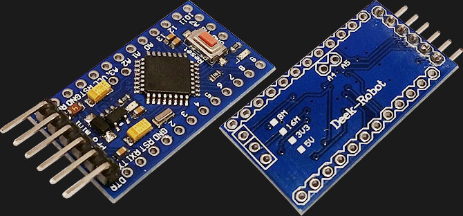
- Deek Robot (Arduino clone) – USD $1.93
- 2-channel relay module – USD $1.90
- Momentary switch with blue LED – USD $7.99
The preparation
I used Fritzing to draw the schematics of my solution which is a great and free tool. This is actually the first time I draw so it probably contain an error, or two 🙂
Fritzing didn’t have Deek Robot as template so I used a Arduino Pro Mini just to show what ports I used.
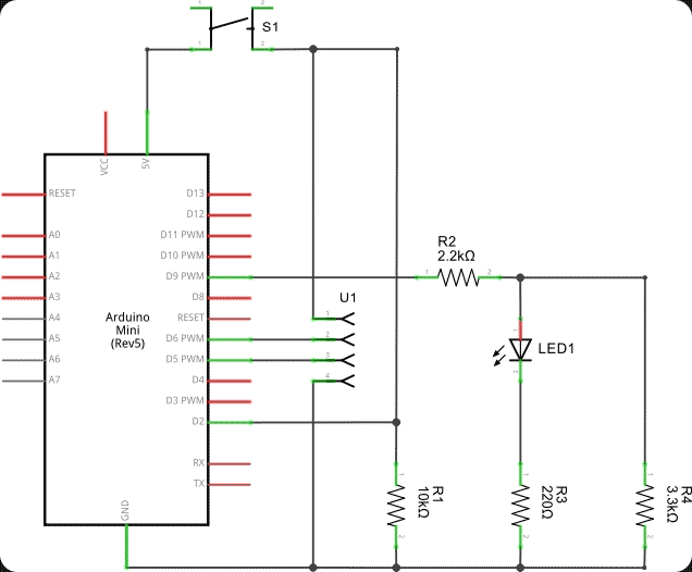
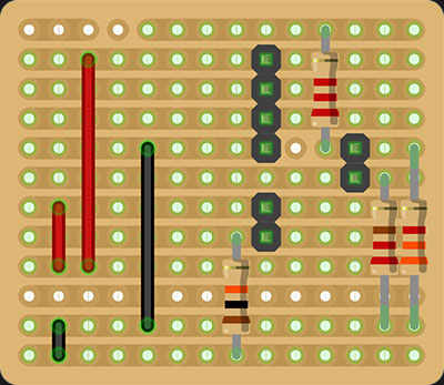
The project will be built on a so called PCB stripboard and the reason why I chosed that was because it would need the least amount of modifications. I used Fritzing once again and the result was the following.
The Arduino
As I mentioned before, this was my first time to design and draw a schematic and it is also the first time I create a program for Arduino. I do like the simplicity of the Arduino. The IDE and all the information on forums makes the Arduino perfect for smaller projects like this one.
No matter if you are a beginner or an experienced programmer, you get started fast and can make your Arduino make amazing things.
The primary goal with my Arduino project was…
- Read the momentary switch and increase a variable each time it was pushed/clicked. The variable should be in the range between 0 and 2 (0, 1 and 2) and then loop back to 0.
- Add behavior on the LED to indicate which status Ratte AMS has.
- Control Ratte AMS jumpers with the 2-channel relay.
The three different states of Ratte AMS would be shown as followed with the LED: Static -> Pulse -> Off
The pulse will be created by a simple sinus curve that has a radius within the PWM (Pulse Width Modulation) limit to increase/decrease the intensity of the LED.
The code
/*
 * Ratte Auto Switch Controller with Arduino
 *
 * mFilos created a similar solution but I wanted to use Ardino which is cheap
 * and very easy to program exactly as you want. The switch has three stages
 *
 * Stage 1 - Auto mode (LED is on always)
 * Stage 2 = RTG only (LED is pulsing)
 * Stage 3 = Amiga Native display mode (LED is off)
 *
 * Created 19 Jul 2015
 * Edited: Never
 * by Claes Brånskog
 *
 * This example code is in the public domain
 *
 *  https://www.ikod.se/ratte-control-switch/
 *
 */

int switchState = 0;
int ratteCount = 0;
int ratteStatus = false;

int ratteVal = 0;

int pulseVal = 0;
int pulseSof = 96;
int pulseDeg = pulseSof;
int pulseMax = 360;
int pulseAdd = 6;

const int ratteSwitch = 2;
const int ratteLed = 9;
const int ratteMax = 3;
const int ratteRelay1 = 6;
const int ratteRelay2 = 7;

int ratteMatrix[3][2] = { { LOW, HIGH }, { HIGH, LOW }, { HIGH, HIGH } };

boolean buttonDown = false;

void setup() {
  pinMode(ratteSwitch, INPUT);

  pinMode(ratteLed, OUTPUT);
  pinMode(ratteRelay1, OUTPUT);
  pinMode(ratteRelay2, OUTPUT);

  digitalWrite(ratteRelay1, ratteMatrix[0][0]);
  digitalWrite(ratteRelay2, ratteMatrix[0][1]);
}

void loop() {
  switchState = digitalRead(ratteSwitch);

  if (switchState == HIGH) {
    if (!buttonDown) {
      ratteCount++;
      if (ratteCount >= ratteMax) {
        ratteCount = ratteCount - ratteMax;
      }
      digitalWrite(ratteRelay1, ratteMatrix[ratteCount][0]);
      digitalWrite(ratteRelay2, ratteMatrix[ratteCount][1]);
      buttonDown = true;
    }
  }
  else {
    buttonDown = false;
  }

  switch (ratteCount) {
    case 0:
      ratteVal = 255;
      break;
    case 1:

      pulseVal = 128 + sin(pulseDeg * PI / 180) * 127;
      pulseDeg = pulseDeg + pulseAdd;
      if (pulseDeg >= pulseMax) {
        pulseDeg = pulseDeg - pulseMax;
      }
      ratteVal = pulseVal;

      break;
    case 2:
      pulseDeg = pulseSof;
      ratteVal = 0;
  }

  analogWrite(ratteLed, ratteVal);
  delay(50);
}
Some explanation
ratteSwitch = Port on Arduino where the momentary switch is connected.
ratteLed = Port on Arduino where built in LED on the momentary switch is connected.
ratteRelay1 = Port on Arduino where Relay 1 is connected.
ratteRelay2 = Port on Arduino where Relay 2 is connected.
ratteCount = Counter between 0 and 3 ( on-off-on ).
ratteMatrix = An array for all the settings for the two depending on what value ratteCount has.
Since I use a momentary switch I need to see that ratteCount is only increased by 1, no matter if how long or short the button is being pushed.
This was solved easily by the following code.
  if (switchState == HIGH) {
    if (!buttonDown) {
      ratteCount++;
      if (ratteCount >= ratteMax) {
        ratteCount = ratteCount - ratteMax;
      }
      digitalWrite(ratteRelay1, ratteMatrix[ratteCount][0]);
      digitalWrite(ratteRelay2, ratteMatrix[ratteCount][1]);
      buttonDown = true;
    }
  }
  else {
    buttonDown = false;
  }
When the button is pushed/clicked we check if buttonDown is False, if it is, we increase ratteCount by 1 and buttonDown is set as True. As long as buttonDown is set as True, ratteCount will not be increased.
The part with “switch (ratteCount)” checks what should be done with the LED, depending on what value there is in ratteCount.
Last but not least, I have added a small delay ( delay(50) ) making it to run 50 times a second 🙂
The assembly
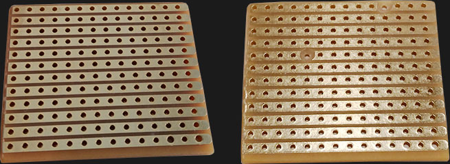
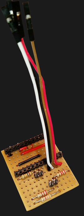
The assembly is easy and straight on. The first step was to cut a piece of stripboard to a size of 12 x 14 holes where the width is 14 holes. Some parts had to be isolated as well and that was made by a 4mm sharp drill (right picture).
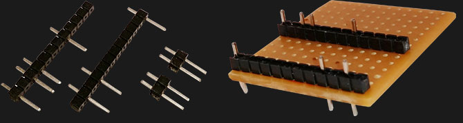
After that the pin strips was cut in correct length and unwanted pins was removed. A pin was left in the upper left corner for stability. But it is also isolated, as you can see on the drawing above.
Next step was to solder the pin strips to the stripboard.
Bridges for both VCC and Ground was soldered with Red and Black wires.
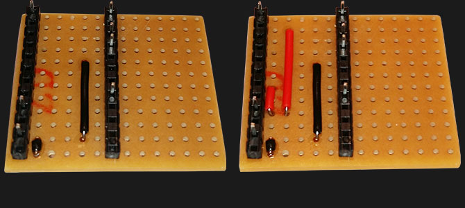
Almost ready 🙂 Now we solder the resistors and also add the last pins that will connect the momentary switch and its LED to the Arduino.
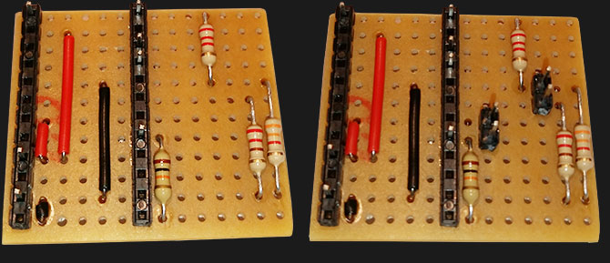
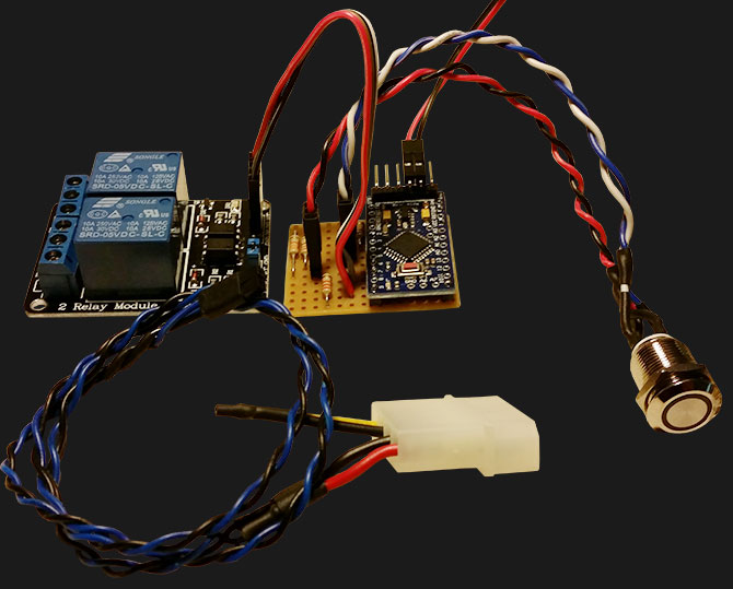
Since the relay module is external, I had choose between pins or directly solder wires. As you can see below, I choosed the wires 🙂
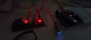
Last but not least, I soldered the Arduino clone in place and then added some cables to the momentary switch. The picture below shows a ready set of the project including a cable for the 5 Volt and Ground.
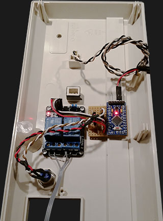
Assembly in the 4000D
There is plenty of room in the front of the Amiga 4000D. All parts fits easily and the standard lock mechanism was replaced by the momentary switch with the built in LED. Some work with the hole had to be done since the inner part of the hole was not cylindrical. This is to prevent the lock to turn while the key is turned.
For those who wonder, the piece of glue stick that can be seen on the below picture is a fix to replace broken/missing fasteners, quite brilliant actually. The black electrical tape is to prevent the LED housing on the front to crack. It is old and some small cracks is visible. Today I have replaced it with shrinkable tubing.
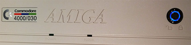
Result
The result is above my expectations. It is simple to switch between Auto, RTG and Native and the blue LED on the momentary switch shows what state Ratte AMS is in. Even if many thought that the blue LED would disturb me, it did not. It is actually very neat 🙂
I also made a small video showing the LED working and put it on Youtube.
Links
- mfilos blog (Original author of this idea/concept).
- Arduino homepage
- Fritzing homepage
Please leave a comment if you have questions or like it 🙂
What an awesome implementation my friend!
I’m so much tempted into working with Arduino, the options are limitless only by imagination.
Thanks also for the reference 🙂
Looking to build this and got all the parts in. I have used your code in the IDE to compile and saved it. What do I use to program the arduino? I got the same one you listed here. Do I just build it with the angle pin header first and connect it using a USB serial programmer?
The first thing I solder to it is the angle pin header and flash both the bootloader and then the code (the Deek Robot is shipped without a bootloader). You can find a tutorial on how to flash the Deek Robot with Arduino here (other ways are also possible):
http://shop.makersmojo.biz/blogs/news/16435055-bootloading-an-arudino-pro-mini