
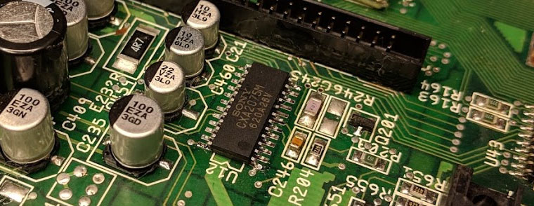
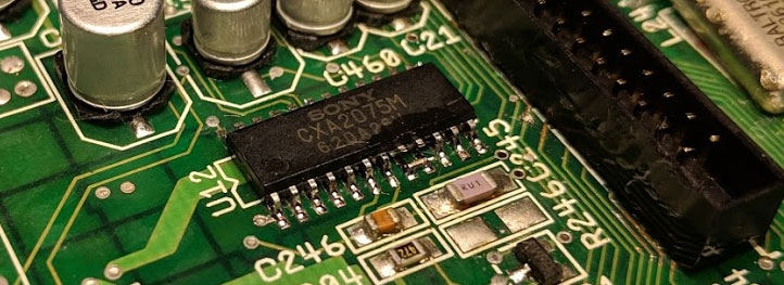
CXA2075M
Lately I have been seeing many Amiga 600 and Amiga 1200 with bad Band Pass Filter (Z221) and Delay Line (Z222). This generally causing bad picture quality on composite and the RF-modulator.
There are many suggested solutions out there but none that really replaces the Z221 and Z222, until now. While attending to Datastorm 2018 I talked some with TBTorro and he said that he had done some tests with CXA2075 which was the high end version of the original CXA1145M which is the one used in Amiga 600 and Amiga 1200.
The modification is rather simple if you have some SMD soldering experience and you only need to components. So, why wait!
Bill Of Material
| Pcs | Component | Type |
|---|---|---|
| 1 | CXA2075 RGB Encoder | SOT |
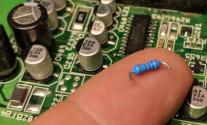
| 1 | 2.61 kOhm 1% Resistor | Through hole |
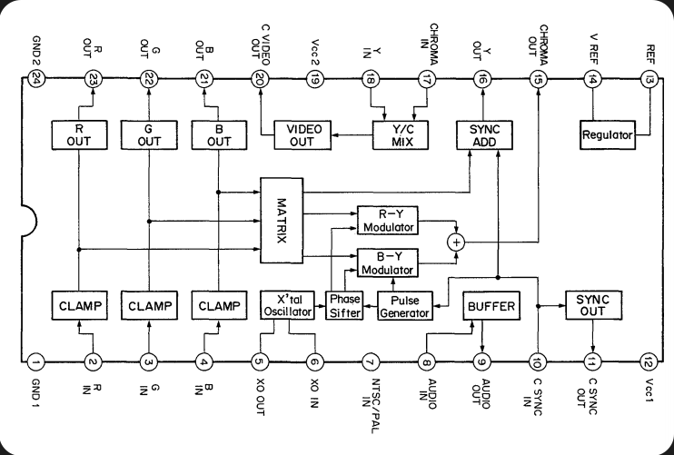
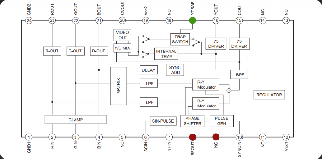
CXA1145M vs. CXA2075M
The pinout is more or less 100% compatible between CXA1145M and CXA2075M. The main concern pins are Pin 8 and 9 on CXA2075M that is Audio In/Out on the CXA1145M and Pin 17 that is where we can enable the internal Trap which acts as the replacement for Band Pass Filter and Delay Line.
Preparation
In my example I will show you how it is done on an Amiga 1200.
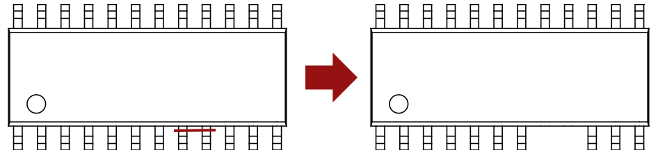
Start preparing the CXA2075M by cutting pins 8 and 9 as the picture show.
Remove the old CXA1145M from the Amiga 600 or Amiga 1200 mainboard. You can also remove Z221 and Z222, but we will disable them so it is really not necessary.
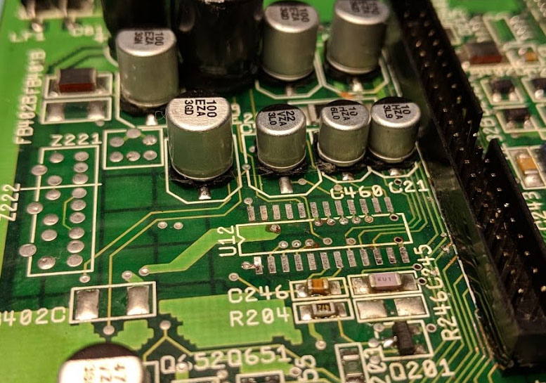
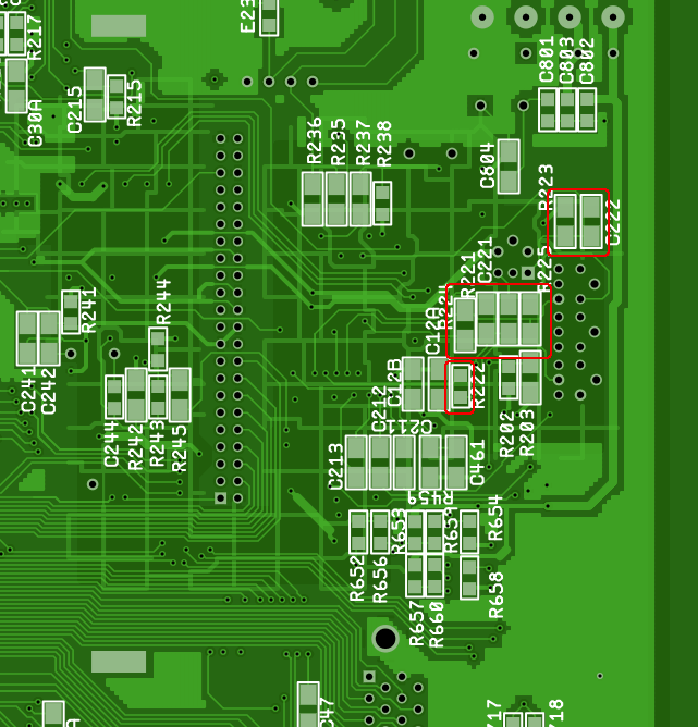
Flip the mainboard on the Amiga 1200 and locate the following area near the IDE 44 connector.
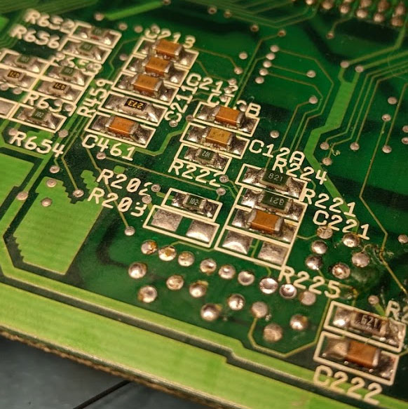
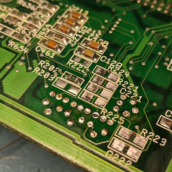
You should remove any of the following SMD components at this area. Note that some of the SMD components might already be removed from factory.
The de-soldering of SMD capacitors and resistors could be looking like this (pre-cleaning). Please be careful when cleaning the pads with solder wick. If you are using to much heat and pressure, you might damage the pads.
Soldering
Clean the pads and add some flux of your choice and then put the CXA2075M in place. Attach one corner with solder, adjust the chip and put some solder on in the opposite corner of the CXA2075M.
When you are happy with the positioning of the CXA2075M, solder the rest of the pins to the mainboard, I these cases I prefer to perform a so called drag-soldering.
As you can see, I have already removed Pin 8 and 9 before soldering the chip onto the mainboard.
When the CXA2075M has been soldered to the mainboard, do a solder bridge between Pad 8 and 9. In my case I used a very short piece of the pin from the resistor.
This can also be done before the CXA2075 is soldered to the mainboard of course.
Prepare the 2.61 kOhm 1% resistor as following. Be aware so you don’t cut the pins too short.
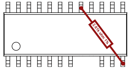
Solder the 2.61k Ohm resistor between Pin 12 and 17 on the CXA2075M. This will add a Pull-Up so the internal TRAP switch is enabled and the CXA2075M will use the internal Band Pass Filter and Delay Line.
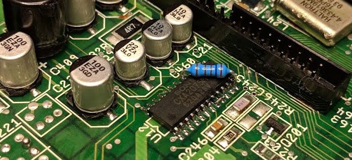
The final result should look something like the picture below. Be sure to connect between the mentioned pins, else you can damage your Amiga.
Testing
Alright, it is time for some testing. I hooked up my Amiga 1200 to a LCD TV with an RCA-cable between the composite port on Amiga 1200 and the LCD TV.
Power on the Amiga… Waiting… Waiting…
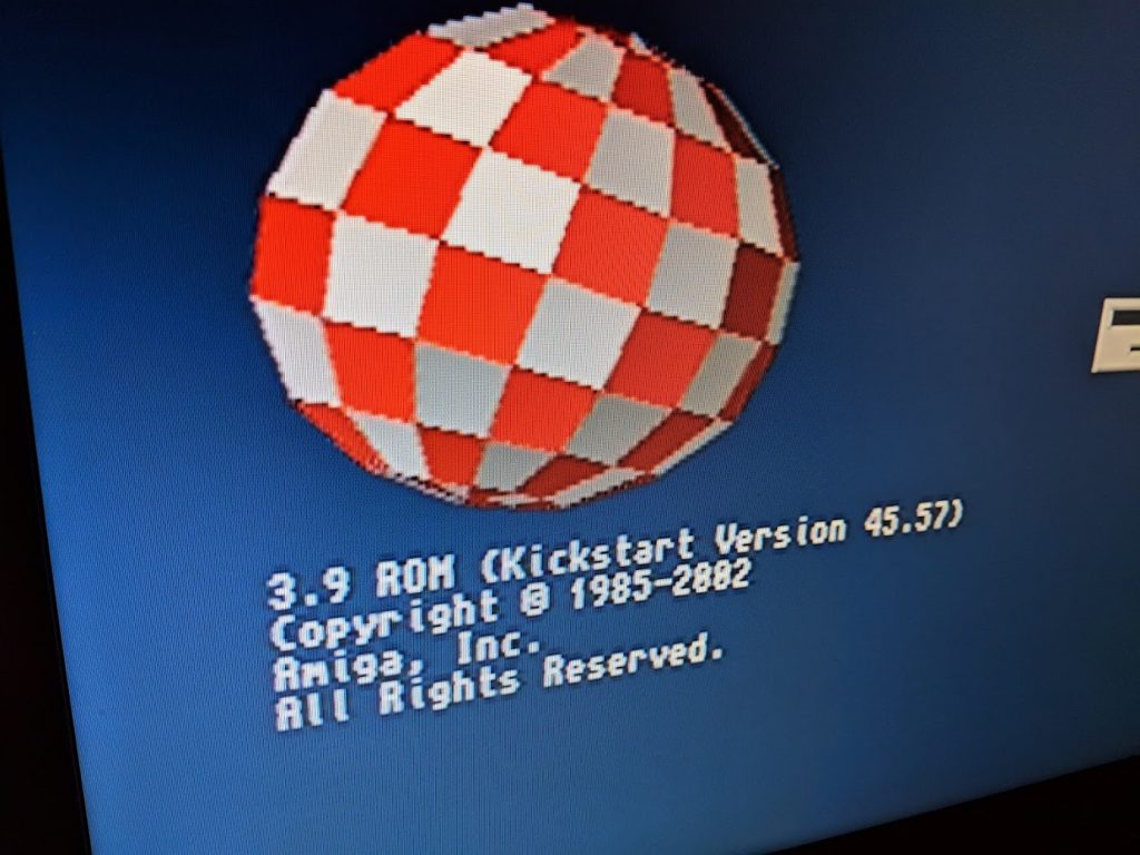
Holy shit! The result was probably one of the best quality pictures with composite I have ever seen. See for yourself!
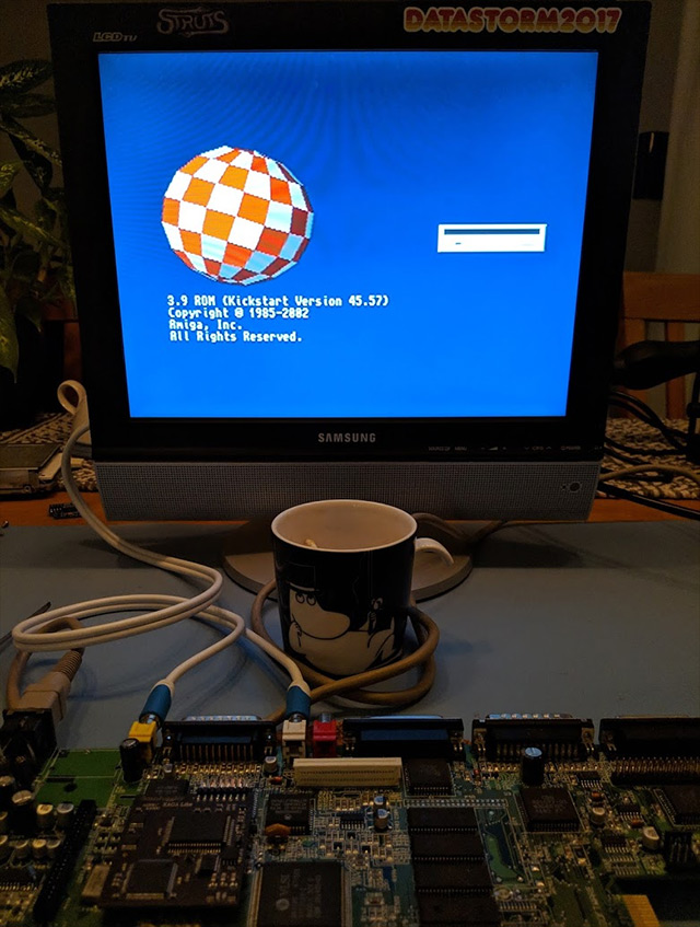
And yes, the Mumin coffee cup is kinda of a thing I do 🙂
Conclusion
Well, I am super happy with this solution. The picture quality on the composite is now better than ever on my Amiga and I have more or less throw away any bad Z221 and Z222 that I find in the future and simply replace them with this solution.
If you have a working composite, please I would say it is not worth it unless you are a perfectionist 🙂
Over and out!
Ohh this is nice stuff! I will look into this when I get the time, so this mod is bether than the 1645 then? Did the rgb out change or is it the same? I also have muminn coffe cup;)
It is a very nice mod. But the RGB out on A1200 does not use the CX1145 at all since it uses the BT101 video DAC. Let me know if do you do the mod and what you think of the result.
I will test this mod for shure 🙂 yeah the RGB just pass-through i guess from pin 2-3-4 to 23-22-21. The C460 cap is it needed anymore? Just need to confirm that it is a 2.61K ohms resistor and not 2.61ohm, in your last drawing there may be a typo. Did you test the s-video out?
Im hoping there will be a FPGA solution soon for the Amiga, tiny board and hdmi out 🙂
Again Nice Work!
I think you could remove the whole circuit around vref and iref for the old CXA1145M. I need to verify. And yes, it is a typo and you write. The resistor should be 2.61 kOhm 1% so I will correct that as soon as I can.
I have not tested S-Video out but will do it later and write a blog about that too. But what I could find was that it has very good quality and you only need to add 4 components.
Still wrong value in the picture. Will it be fixed any time soon? Next Wednesday?
I did not mention exact year 😛 But now it is done.
How get SVideo signal out to put a conector jack ? GOOD JOB
I’m working on a solution still for that. Did a test PCB and the picture was perfect 🙂
You can buy S-video PCB kit on Amibay. It uses just two capacitors (220uF) and 75R resistors.
With 2075 chip you probably do not need to recap C459 22uF as no longer used. I will check and confirm next week. C214 can be replaced with 0R.
With RF removed, you do not need following caps: C214 (audio mono input), C235, C459, C236, C239.
I already did similar fix to my CD32, and is working great.
Now I’m working on my A1200 with S-Video PCB kit.
Do you know a reliable source of CXA2075M chips? They only seem available from Chinese sellers.
I usually buy them from utsource.net, for example https://www.utsource.net/itm/p/1332076.html . Just be sure that the seller is “Utsource”, else you might get bad/rebranded IC’s.
https://www.ovaga.com/
Ovaga provide various parts, you can go to ovaga and search the part.
More IC chips you could found from avaq semiconductor , a Hong Kong IC distributor https://www.avaq.com/category/integrated-circuits-ics
Can i use 2.7 k resistor ? i cant find here 2.61 k not easy .Thanks.
I followed the specification and that says 2.61k so I have not tried any other resistor. Can do the next time I do this mod but I do not know when that will be 🙁
if the precision is 10-20% then yes you can. Anyway there are always a bit off. It’s role is only to limit the current to minimal and still have the pulled voltage on the pin
I cant get images from composite and/ or RF , but yes by RGB , i purchase CXA 2075 for this mod, is possible to restore composite output with this change? The resistors from bottom pcb MUST be take off, or can i leave them.?
Thanks
Which Amiga model did you do this with and also, are you 100% sure that you removed the correct SMD’s on the bottom side?
I did this mod and it was working fine initially, then something broke and I began having a weird video issue, both from the RGB and composite port, watch this video to understand:
https://www.youtube.com/watch?v=TD8v7PcVHCY
Note that every few seconds, an “almost correct” image shows up for a microsecond. You should be able to recognize Systest.
It is NOT a problem with the new encoder, as I have proven that the bad signal is coming out straight from Lisa.
I have already checked all the lines from Lisa and they look fine to me.
Caps are fine too.
The 28 MHz signal looks quite bad on a scope, but it looks the same as on another A1200 of mine, so I guess that’s OK.
Any hints? Faulty Lisa?
That is very wierd. I will have a look at it as soon as I have a minute over (work 🙁 )
Thanks a lot! I’ve discovered something new: DiagROM starts up correctly, but when the screen should switch to 320×200 everything gets corrupted. Could this confirm a faulty Lisa?
Video is here: https://www.youtube.com/watch?v=lKffQXvYcqo
Sorry, not to 320×200, but rather to lowres 32 colors.
That looks like either a bad Lisa or some solder joint. Have you tried a re-flow of Lisa? Other error like sync signals usually looks in an other way.
Well, I have checked all signals coming from/going to Lisa against a working board and I cannot see any obvious differences. I guess I’ll try replacing Lisa, sigh. Thanks for your help.
Finally fixed this, it was due to a bad Alice (not Lisa!) chip. It was probably damaged by the dodgy power supply I was using at that time.
Also tested this mod on a couple of A600, works great!
Thanks for sharing :).
Oh! Nice to hear 🙂
How did you find that it was a bad Alice chipset?
You don’t really wanna know ;).
(Socketed all chips and tried known-good ones.)
I ran across this post while reading info about this chip and how it functions. This was a good result for the final product! Nicely documented too, thank you.
I’ve replaced the Samsung SKA2195D in my Sega Genesis model 2 with a CXA2075 and I was very impressed with the results on S-video. Now looking to get one working in a Super Famicom thatt I’ve already modified for YPbPr output
I have a CD32… Would replacing the CXA1145 with a CXA2075M also improve the quality of the standard S-Video output, because it’s better than composite, but not as good as I’d expect S-Video to be?
Sorry for the delay. I have not tried that, but I do know someone who has. I will try to find him and ask.
i have to leave smd on back when i mount new CX2A2075M on Amiga600?
I have not tried the modification on an A600, but probably you need to do similar work.
This works great on the A600.
I did this mod too on A600 but the signal is at the most the same as before, not better. Maaaayyybe even a little worse. So basically I am fine but I expected a clearer result and the screenshots seem to show a better image quality than before.
The 2.61k Resistor I got is 2.58 (I tested ~20 of 100 which I bought and they are all between 2.57 and 2.58) – might this be the reason since it is more than 1% off?
But maybe it’s just my china tacklife multimeter which is not that good…
Best
Jon
which component do you have remove on back main board to work perfectly on A600?
on CD32 is possible this mod?
which component on mainboard BACK i have to leave?
Hi, I would like to make this mod for my amiga 600 tell me how to proceed?
Thanks
Great blog entry, thanks for sharing.
I performed this on my Amiga 600 successfully. As per this blog entry removing the smd parts is just to disable the 221 and 222 square metal cans.
So you can do what I did and remove the 221 and 222 parts ( you do so at your own risk ).
https://8bitshardway.blogspot.com/2020/08/fixing-video-on-my-amiga-600-after.html
Freakin awesome! Thanks for sharing 🙂
Thanks so much for this mod. I decided to make a video demonstration of it. I hope it’s of assistance to someone out there:
https://youtu.be/e2QI1_YjQSo
Wonderful! Love the video 🙂 Is it OK if I link it to this page?
Thank you and of course!
Hi there,
I performed this modification on my A1200 Rev. 2B motherboard, primarily because Z221 and Z222 had failed, and I followed the instructions very closely. By and large, while it does work, I find that the CXA2075M gets very hot to the touch to the point that you can’t leave for your finger on it. Is this normal? I also found the picture to be a little worse than before with increased spider effect around edges of objects.
The CXA2075 gets a bit hotter than the original. I will do some tests later on where I measure the temp with a FLUKE heat camera.
That would be awesome!. Thank you very much. And thank you so much for this guide as well!!
So to just follow up on this:
I was initially concerned that the 5 Sony CXA2075M chips I bought were fake (I later found out that they were actually genuine but definitely second hand).
I found a supplier who sells genuine NOS of these chips and replaced the first CXA2075M, that I originally put in, with one of these. The result is the same, the chip gets intensely hot to the touch. I measured with a Flir heat camera and it says it is running at around 98 degrees Celsius, same as the first one. I’m not 100% sure how accurate that is.
It may still run just fine being so hot, but I’m wondering whether there is something about the 2B revision of the A1200 motherboard, as opposed to something like the 1D4, that causes it to run this hot. I double checked all my work against this article, especially the removal of the SMD’s at the back of the motherboard and all is correct.
Any ideas?
I have not been able to test it on a 2B version yet, but will try to find one or at least the reason why it runs so hot. If you also find something, please let me know.
I did the mod in two A600 (chips run cool), and one A1200, rev 1D1, and it gets very hot. I’m not sure what is happening, but I’ll try to measure all input signals to see if they are distoted somehow (the heat may be due to some kind of signal reflection / impedance mismatch), but I’ll try to see if the output is lower impedance on the A1200, which might lead to higher output current. Any other ideas for tests / measurements? Since I have two A600 with the chips running cool, I can scope both and compare.
This comment is in reply to Eduardo’s comment (as the comments section doesn’t seem to allow more than 4 replies in the chain):
That would be great if you were able to do more tests. Unfortunately, my knowledge in this area is limited and I haven’t been able to get help from any other sources despite posting on several forums. Something is definitely not right here as the chip should not be getting this hot.
I’ve held back from using this motherboard as I don’t want to risk any damage until the cause can be determined.
Please let us know how you go. 🙂
@Sean_sk did you fix your temperature issue? Did you try CX1645 fix instead? Is it hot as well? I observe the same issue on 1200 r1d and think to try to decrease voltage on pin 10 and pin 17.
Hi! I’m doing this mod on a A600 right now. I wonder If The list of components To be removed on The backside is The same as on The A1200? Their position is different on The A600.
Cheers
M
I need to update this page with that ASAP.
Hey, i would just like to replace these z222 and 221 components, but has any1 idea where to buy them?
They are really hard to find and has been discontinued for a very long time. That is why this fix exist.
I have just done this mod on my CD32. Although i just removed the ZZ filters and R224, R225, R223 and C222, but it works a treat.
Nice! Thanks for the information. I was thinking of putting up a guide for A600/CD32 as well.
Great mod. I had an A600 with no composite output due to faulty delay lines, now fixed! The 2.61kOhm resistor seemed to be too much on my Amiga, the internal delay circuits didn’t seem to be engaging. But after dropping down to a 2.2kOhm resistor it works great.
Great, perhaps I should add a notice saying that 2.61 Ohm might be too much and that they should be ready to have 2.2 kOhm – 2.61 Ohm on hand.
Maybe you should add this info from the sony datasheet to your BOM:
Internal Trap Resistor PAL = 2,61 kOhm 1%
Internal Trap Resistor NTSC = 3,32 kOhm 1%
But, why does it not work with 2,61k Ohm on some machines? If datasheet says 2,61k it has to work with 2,61k.
Hi,with this mod works on RF and rca VIDEO mode?
RCA (Composite Video) works but have not tested RF, should work thou since the cvideo is intact.
used it for A600 and it works great !! Thanks for this rework !!
Hummm.
Tested on 2 Amiga1200 (rev different)
so couple of CXA2075M + 2.61Kom
Same ‘issue’, picture does not have enough red.
Check if change resitor change this…. nop
Any idea ?
RGB values measured on cxa are correct.
Hi,with this mod the RF out keep working? or lost?
Censtry is a company that operates as an electronic component distributor. As of my last knowledge update in January 2022, I don’t have specific information about Censtry, and I cannot access real-time data or websites. However, electronic component distributors like Censtry typically play a crucial role in the electronics supply chain. They act as intermediaries between manufacturers (of electronic components) and customers (such as businesses or individuals in need of these components).
https://www.censtry.com/
Automotive electronics refer to the electronic systems and components integrated into vehicles for various purposes, including control, communication, safety, entertainment, and performance enhancement. Over the years, the role of electronics in automobiles has grown significantly, contributing to the efficiency, safety, and overall functionality of vehicles.
https://www.nevsemi.com/