
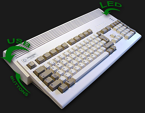
A1200 + GOTEK
![]()
I made a GOTEK-mod for a friend of mine with his Amiga 1200. Before I got my GOTEK so I could measure and plan the modification I was quite horrified from all the pictures that flows around on different forums.
My main goal was from the beginning to make a nice and as “invisible” mod as possible that would blend in to the main look of the Amiga 1200. After after about 30 hours of hard work, alot of investing in tools for the mod, this was the result.
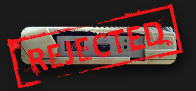
Enough with the jokes… My plan is to put the LED-display of the GOTEK just above the PWR/HDD/Floppy-LED by making a rectangular hole and put the USB-connector and buttons on the left side seen from the above of the Amiga 1200.
Mounting the GOTEK
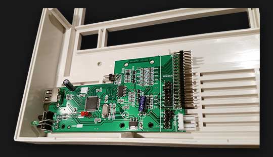
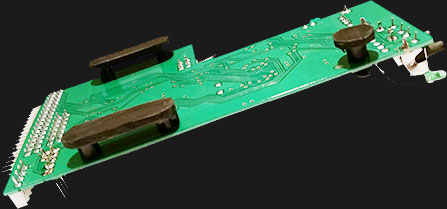
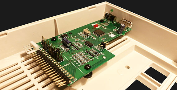
The first challange was to find a good way to fix the GOTEK PCB inside the upper housing of my Amiga. Usually this was mostly done with glue and other sticky obstacles, but I wanted it to be easily removable. The picture below shows how the PCB will be fitted when it’s done.
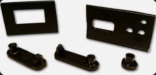
An idea popped up and due to the fact that I was not going to use the GOTEK housing at all I could use the bottom plate and it’s mounting holes. After some measuring I found that it would work I started to make guide-lines and cut up as planned. Since I only have use for the elevated parts and the front panel, those are the parts I will save.
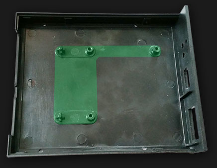
The end result was better than expected and with this solution I could easily remove the GOTEK later if needed and also keep almost the same airflow as before, which is very important to my other project with cooling.
Using the original housing as template
Since it is almost impossible to mark the holes by just measuring on the housing of the Amiga. This might be a good-enough solution for most of the people but why not do it the best way possible while you’r at it.
By using the original housing of the GOTEK drive, we can easily have a goof fixation and pretty good accuracy when we make the holes. The down side is that we have to work from the inside and out.
First we mount the previously modified and removed mounts from the GOTEK drive to our GOTEK PCB as the picture below shows. Please note that the screws cannot be fixaded perfectly without making them shorter.
The next step was to make the part of the USB and buttons panel attachable to the inside of the Amiga. Simple solution, use double grip tejp as the picture below.
After that, gently position the panel to the GOTEK PCB and put it in place on the inside of the Amiga. Then slide it carefully until it get stuck inside of the house as the picture below.
Gently press the front panel to the inside of the Amiga but avoid putting any preassure on the GOTEK PCB. If it doesn’t stuck at all, a cleaning with for example isopropyl alcohol.
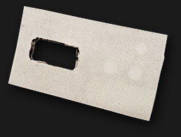
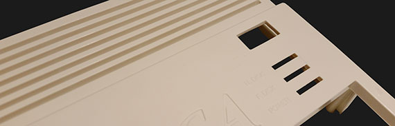
When the PCB are removed the result should be that the front panel is set inside the Amiga like the picture below.
The holes for the up/down buttons and LED was made by drilling, no need to do it harder. The USB-hole is harder to get right, of course it is much easier to do with the template in plastic.
Start with drilling a few holes in the area that will be removed. A good advice is to keep away from the edges because margins is your very best friend. After that, do some fine work with the crafting files and fain grained sand paper.
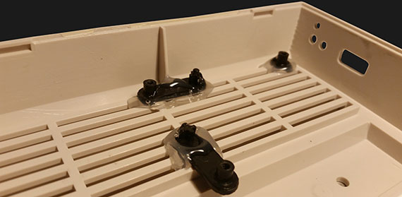
When this is done, the job of putting the GOTEK-mounts pads into place started. Remember to cut the original screws else they will be too long. A smaller issue is that one of the mounting pads ended up outside the Amiga 1200 housing so I had to turn it 90 degrees and cut away the small top (you can see it on the closest pad in the picture below).
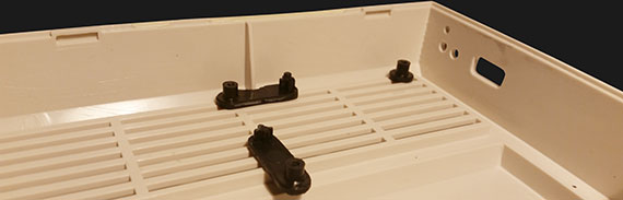
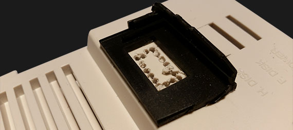
When the pads were mounted on the GOTEK PCB, I put glue on the bottom and gently placed the PCB in place. Remember to put it down in an angle, else it will get stuck in wrong position!
Finally, when the glue has hardened I decided to be extra safe and put melted glue as well. I rather have some nasty boogers inside my Amiga 1200 then a loose GOTEK PCB 🙂
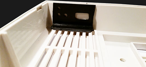
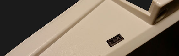
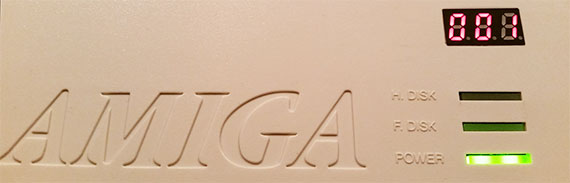
The LED-display
Now to the perhaps hardest part. Why so?
Well, this is the most visible part of the GOTEK installation and it will be in your sight each and every time I sit with my Amiga. If the hole is too small it will be no problem, the problem is if the hole is too big, the shadings etc will occur and it will look bad.
I used the same technique as I did with the USB-connector. Double grip tejp and then I put the panel-template where I wanted it. Drilled “a few” holes in with some margin inside of the template.
After that, there must have been at least 40-45 minutes with filing. One common mistake when it is nearly finished is to not to try the LED-display in the hole. The closer to finish you get, the often you should test.
When it fits like a glove, round the sharp corners with a fine grained sand paper. BUT NOT TOO MUCH!
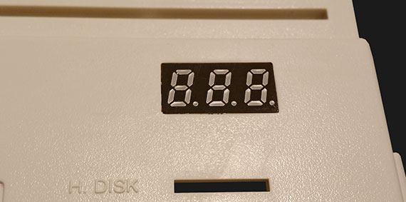
And the final result with both Amiga 1200 housing and the LED-display…
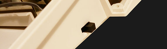
The switch hole!
Ok, that sounded kinda dirty! But I did need to do a smaller hole for the switch that I will use to switch between the internal floppy and GOTEK. I used a pretty standard one that I found on electrokit and then a template was created fast in a standard drawing application.
The actual hole from the switch was also cutout since this was not in the GOTEK panel. When the template was applied, an ordinary non-removable pen was used to mark the position and where to cut.
A few holes later and some work with the tools the result was satisfying enough to assemble the switch. In this modification I use a 2 way 3 pole switch, but a 1 way 3 way pole would be enough.
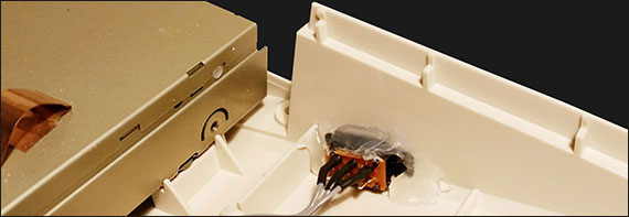
Hot glue is your best friend, or what is your opinion?
As many other projects that I have made, the hot glue is a important tool and component that is a part of the success. The switch has 3 connected cables and those are.
- DS (Disk Select) from the internal floppy connector in the Amiga 1200.
- DS (Disk Select) going to the internal floppy.
- DS (Disk Select) going to the GOTEK.
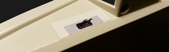
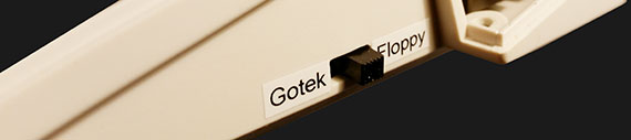
Fixed some labels that clearly showed what is active at what direction of the switch. I would have preferred a transparent background but it was not available at the moment.
Cable time
Alright! It is time for some soldering and cable workshop. I need to fix a Y-cable for the floppy and a dual floppy-cable where I cut-out cable 10 (Disk Select) and re-route to the switch. The Y-cable is not hard at all, just split it and keep it to the colors and choose the correct length so it will reach the GOTEK that is located on the other end from the floppy.
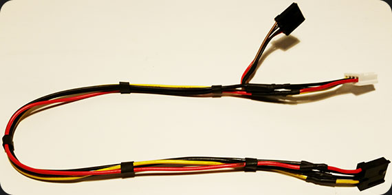
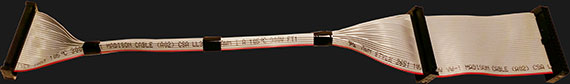
The floppy cable isn’t hard to make when you have a IDC crimp tool. I chosed to split the cable in group of 5 wires so it would not block any airflow. It does not matter on what side you set the 34 pin floppy connector, as long as pin 1 is pin 1.
[imageeffect type=”lightbox” align=”aligncenter” width=”540″ height=”155″ alt=”” url=”https://www.ikod.se/wp-content/uploads/2015/01/gotekfloppycable.png” ]
Putting it all together
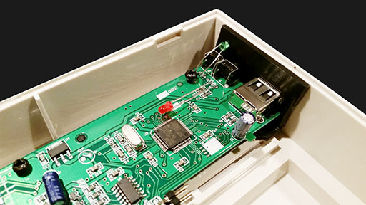
It is time, the switch, GOTEK is in their place and the cables are ready. Putting it together is the easy part and also the most thrilling one.
Will it work?
[imageeffect type=”lightbox” align=”aligncenter” width=”570″ height=”222″ alt=”” url=”https://www.ikod.se/wp-content/uploads/2015/02/gotekinstalledandready.jpg” ]
Conclusion
Well, I can say that it is worth it to put the extra time so it will be a nice and clean installation. You do not have to go crazy on you’r Amiga to install a GOTEK. Totally I spent about 3½-4hrs on my project and it turned out great.
Thanks for taking you’r time to read this blog through. If you like it, please leave a comment 🙂
Looks really nice. Would you consider doing this as a service? I would probably be interested if you would 🙂
Hi Adam,
As it is now I quite busy and I don’t have any GOTEK’s at home. But perhaps I can be at help later 🙂
Thanks for the inspiration!
Did my own mod and did some changes like moving the LED’s to where the other LED’s are.
http://sv.tinypic.com/r/2cy1oc6/8
Thans for doing the most of this mod a breeze!!!
Awesome mod! Didn’t think about that myself 🙂
Hejsan!
Och jag ber redan nu ursäkt att jag kommentera på fel projekt
MEN jag har precis fått hem min gotek och jag lyckas ej med flashningen. Jag antar det är min kabel jag har skaffat som strular. Så min fråga är när du bootar upp med “flash enable”
syns det på displayen? Min blir blank.
Mvh
Emanuel
Displayen visar inget när GOTEK är flash-enable. Vad är det strular, får du inte kontakt med din GOTEK?
can you post or send me some instructions about the switch gotek-floppy. If you could send me some images it would be perfect.
Anyway.. thank you for your help
I’m not quite sure what you asking for here. You want instructions on how to make the cable or?
yes.. the connection from the switch to the cable. You talked about 3 conections.
DS (Disk Select) from the internal floppy connector in the Amiga 1200.
DS (Disk Select) going to the internal floppy.
DS (Disk Select) going to the GOTEK.
sorry for my questions but i dont know many things about amiga. Just this month i try to understand it. Thank you for your time. i liked very much your project and i try to do this to my 600.. i hope so..
No problem at all. Made a quick picture on my lunch that hopefully gives you the information you need.
https://www.ikod.se/wp-content/uploads/2015/11/GOTEK-Switch-Connect.png
🙂
Thanks for this MOD!
just did it and my Floppy disk doesn’t recognize and disk.
I can hear the TAC TAC then floppy check, and I have the ROM picture showing insert disc.
any idea?
forget it!
Just founded that my FD is dead.. swapped to a new one and works fine!
Been there, done that 🙂
Where did you get the dual floppy cable to connect the amiga floppy, gotek and Amiga 1200 together?
I made the cable myself with IDC 34 connectors and a flatcable.
In the picture labelled “gotekswitchglue” what the three black thinks covering the wire where it joins the connector on the switch. Presumably it is covering the solder where you connected the wire to the switch?
That picture actually has the unaltered cable. The 3 black stripes are just to hold the cables together. The order of the cable pictures are:
1) Cable with connectors and stripes (no DS hack included)
2) Drawing of the DS hack
3) Installed cable with the DS hack included
Hi admin,
I just put on my gotek article, a reference of this post with your awesome work.
http://arananet-net.kinja.com/tuneado-una-gotek-para-instalarla-en-un-commodore-amiga-1767360756
Regards,
Edu.
No problem 🙂 Thanks for your comments!
Thanks very much for the this mod, it’s excellent. I’ve run into a bit of a problem. My original Floppy drive a Chinon FZ-354 developed a problem. I bought a Samsung SFD -321B (http://www.techtravels.org/wp-content/uploads/pefiles/SAMSUNG-SFD321B-070103.pdf) and modded it to fit my Amiga 1200. When everything is connected the Selector.adf in to gotek will not load when the Samsung SFD-321D is plugged in. When I unplug the Samsung Selector.adf loads. Could you point me in he right direction? Could it be there is missing pin 3 or 4 (not sure how numbered on the samsung)?
Thanks.
Pin 3 has no connection on the Amiga 1200, and pin 4 is connected to pin 16 (motor) on the floppy connector (IDC 34). Have you done the cable as my schematic shows? It should only be using wire 10 which is DS0, if so, how have you configured your floppy? DS0 or DS1?
I followed your schematic exactly. I modified the Samsung drive as post no 9 on this website (http://eab.abime.net/showthread.php?t=30944). This I think would configure it to DS0, the Gotek’s jumper is also set to DS0.
The Chinon FZ-354 that I had when this setup was working was DS0.
Unless I have missed something.
Thank you.
I need to find such floppy and test for my self. It should not be a problem using this solution so I’m curious what might cause the problem you are seeing.
I modified another Samsung drive, it now seems to be working OK. Not sure what the problem was with that.
Hi admin,
I just finish my A500+ modding. I put a reference of this post with your awesome work.
http://arananet-net.kinja.com/instalacion-interna-de-una-gotek-floppy-en-un-commodo-1768685706
Regards,
Edu
This is so cool!!! Do you have a diagram showing which wires go where for the switch to floppy/gotek/1200?
Thank you 🙂
It depends on the switch. The one I used had the pin-out “Out 1 – In – Out 2“. So I connected DS0 from the Amiga to “In“, GOTEK to “Out 1” and the standard floppy to “Out 2“.
Hope this helps 🙂
hello, assemble the cable as explained for use in an A500 and A1200 and works perfect. Arme another cable to another A500, and something weird happens, the drive works perfectly, but the Gotek not work. I test the drive side of the gotek and works, the back to try the other side and it works. I taste the gotek to replace the floppy drive, and it works, I test the gotek the other side and does not work ….. do not understand why the floppy drive walks in either hoses, and gotek only one. The floppy drive is not original commodore, is a reformed pc.
The gotek the probe as DF1 and DF0 …. do not understand why it does not work as it should.
Any ideas? I’ve tried everything.
Regards!
Very strange indeed. Do you have a chance to test with another GOTEK-drive to see if it can be isolated to just that GOTEK-drive?
Hi, very nice mod,
I will do this to my a1200 as well pobably, but at the moment i cant get my a1200 to run the selector.adf, with even onlythe gotek drive.
Do you know this problem?
Which firmware revision did you take?
Currently I’m only using the HxC firmware (non free) but have you tried different types of USB-sticks? the GOTEK can be and is normally VERY picky.
Maybe some1 can help me. I’ve done the mod on my A500, but when both gotek and fdd are connected, only the fdd is working, regardless of the switch position. I’ve connected the cables to the switch as shown in the schema, but I’m using a different switch. It’s a standard “2 position” switch with 3 wires. I must have done something wrong.
http://sv.tinypic.com/r/mtsbuw/9
http://sv.tinypic.com/r/2vjd47k/9
Hi there folks.
Any hints on how to do the wireing on this particular switch ?
http://sv.tinypic.com/r/mtsbuw/9
http://sv.tinypic.com/r/2vjd47k/9
I’ve connected it following Admins schema, but I only get the floppy working regardless of the switch position. 🙁
So, this is what I did. Hope some1 reads this soon. Thanks.
http://sv.tinypic.com/r/23hnf69/9
All is working now. I counted the wires from the wrong end of the cable. Plus, I was using the twisted cable, so I had to open it and make it streight.
Hi,
Hätte da eine Frage. Wenn das Kabel auf das Floppy (Intern DF0: ) steht, wird dann das Gotek auch als Df1: benutzt und umgedreht, sprich Booten von Gotek df0:.
Will nur wissen ob man auch zwischen denn beiden Laufwerken auch Kopieren kann oder ob mann dann zwingent noch ein externes Laufwerk braucht ?.
mfg
Sorry, no translation 🙂
Hi,
Da had a question. If the cable to the floppy (Internal DF0:) is that Gotek is then as Df 1: used and reversed, that is booting from Gotek df0 :.
Just want to know if it also included among the drives also can copy or whether man then zwingent still need an external drive?.
mfg
Hi IRon,
This hack is only for swapping between the standard 3.5″ internal floppy and a GOTEK. If you want to use the GOTEK as a external DF1: as well you need to do some modifications on one of the CIA-chipsets. I did a solution earlier where I used an external GOTEK and by the keyboard I could swap role of DF0: and DF1: between the internal floppy and external GOTEK.
Perhaps that is a better solution for you.
I’m curious about switching DF0: and DF1: using keyboard. Can you link the solution? Thanks!
I have all files and so here but not published in a blog. Perhaps I have time for this later.
Hi, I was wondering if you can give advice about the mod with a standard PC IBM floppy cable. I was able to find only the cable for PC, which has a twist between the second and third connector, to support drive A and B, while I assume that the cable you made is straight and without the twist.
I have the cable but before cut it I want to be sure that I am doing this right 🙂 Thanks
The cable is straight so the easiest way to do it is just to re-twist the PC-cable 🙂
This guide is great! Can you recommend an IDC crimp tool?
Thanks!
I bough a “cheap” version from http://www.rs-online.com with part number 235-6428. That has served me well over the past few years.
Riscman on ebay does some of the best 3D printed brackets for these mods -v nice
https://www.ebay.co.uk/itm/183785036479
https://www.ebay.co.uk/itm/183700641443
Very nice! I’ve seen many good solutions over the past months. My personal favorite is when you see the display easily on top of the Amiga. I think there is some solution where you route the cables through the ventilation and then has a 3D-printed cage for the LED-display.
Can you please make one for me I will pay you for parts and postage & for doing it, I cannot do one myself. I cannot find anywhere that sells them, and would love one in my 1200.
Make a cable? Or the whole set?
This is a really tidy job, and hot glue rules. 🙂 I have an OLED Gotek and was going to put it in a real external drive case, as I didn’t realise there might be room to fit it above the internal floppy.
I would be interested in the drive cable, or at least the length and spacing of the connectors. Thanks.
It is all packed now due to moving but I will arrange it for your ASAP.
Hi!
First of all, thanks for sharing your project, it has been of great inspiration for me.
The only thing that doesn’t suit me is to modify the original A1200 case, so I’ve designed an external box, passing the cables through the case slots and putting it on top of the computer. You can see it here:
https://www.thingiverse.com/thing:4776648
Of course, your project page has been properly linked. Also, I hope you don’t mind I have used your image of the cable schematics.
Again, thanks.